During the last weeks, we had a chance to work with the VMware NSX for Multi-Hypervisor (NSX-MH) software defined networking solution.
In the following post, we want to focus on how to integrate physical servers or network devices like firewalls, IDS/IPS, loadbalancers in the NSX overlay networks with VXLAN VTEP enabled switches. Multiple third-party vendors provide NSX gateway service integration already. Please note, that currently, only L2 gateway support is available. The native NSX gateways provide L2 or L3 Service capabilites.
As the underlay network is backed by Arista 7150 switches, we wanted to see the Arista VXLAN VTEP L2 gateway implementation in action.
We are using an OpenStack project to provision some virtual machine instances and networks. The NSX neutron plugin, configures the logical switches and switchports on the hypervisor switches through NSX controller API calls.
The goal is to bring a physical server in the same logical switch that was provisioned through the OpenStack neutron plugin. The Arista Switch VTEP, terminating the VXLAN tunnel to a VLAN, enables the physical server to communicate with the OpenStack instances transparently on the overlay network.
Usecase overview:

Here are the configuration steps necessary to make this work:
Arista VXLAN VTEP Gateway Switch Setup:
First we have to enable the controller agent on the switch and associate it with the NSX controller.
Enable the controller agent on the switch:
arista(config)#cvx
arista(config-cvx)#no shutdown
arista(config-cvx)#service vxlan
arista(config-cvx)#service nsx
arista(config-cvx-nsx)#manager 10.10.10.10
arista(config-cvx-nsx)#no shutdown
arista(config-cvx-nsx)#exit

arista(config)#management cvx
arista(config-mgmt-cvx)#server host 127.0.0.1
arista(config-mgmt-cvx)#no shutdown
arista(config-mgmt-cvx)#exit
Configure the VTEP:
arista(config)#interface loopback 15
arista(config)#ip address 10.10.10.100/24
arista(config)#exit
arista(config)#interface vxlan 1 (Note: VTEP Number)
arista(config-if-Vx1)#vlan source-interface loopback 15
arista(config-if-Vx1)#vxlan controller-client
arista(config-if-Vx1)#exit
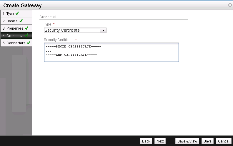
Display the NSX SSL certificate:
arista(config)#show nsx certificate
...
-----BEGIN CERTIFICATE-----
...
-----END CERTIFICATE-----
Copy the text starting and including —–BEGIN CERTIFICATE—– —–END CERTIFICATE—–
This information is needed to used certificate based authentication when we add the gateway in the NSX manager.
Configure the Server access Port:
arista(config)#interface Ethernet10
arista(config-if-Et10)#physicalServer
arista(config-if-Et10)#switchport access vlan 200
arista(config-if-Et10)#spanning-tree portfast
arista(config-if-Et10)#exit
NSX Configuration.
On the NSX Manager we have to complete the following tasks to enable connectivity between the physical server and the VM’s in the overlay network:
- Create a gateway
- Create a gateway service
- Create the logical switch port.
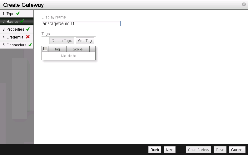
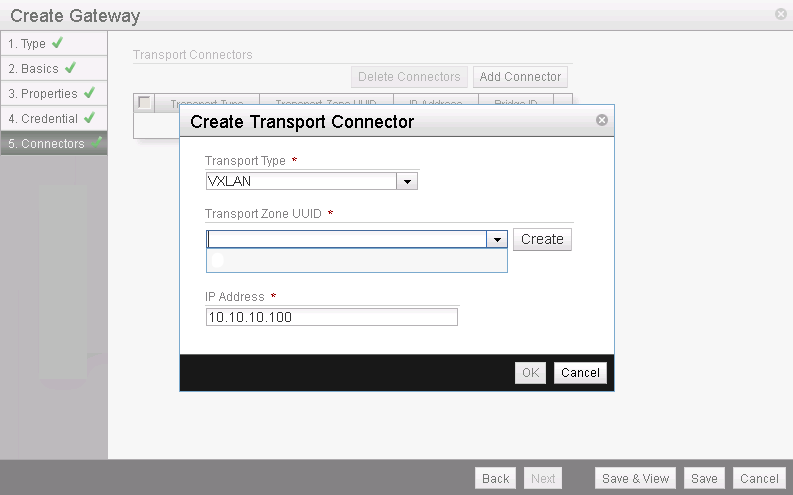
Add a Gateway

Transport Node Type: Gateway

Provide a name for the gateway

Check “VTEP Enabled”
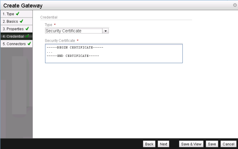
Paste the certificate value we dumped from the arista switch.

Transport Type: VXLAN
Transport Zone: The UUID of the underlying transport zone
IP Address: Transport Zone IP of the Arista Switch
Click Save & View
Add A Gateway Service
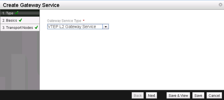
Gateway Service Type: VTEP L2 Gateway Service


TransportNode: The Gateway ID of the GW we created above
Port ID: Choose the physical Switch Port we want to use. In our example Ethernet10
Click Ok – Save & View
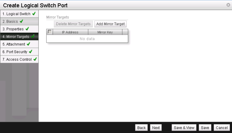
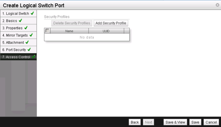
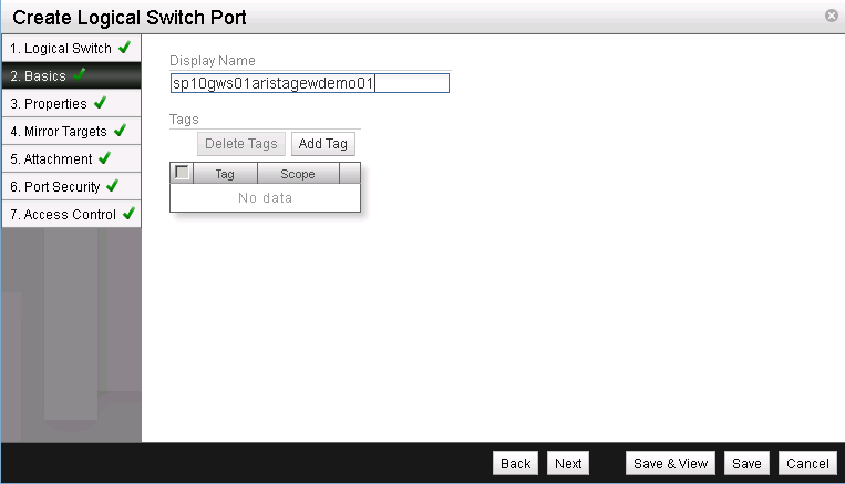
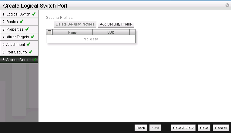
Add Logical Switchport on the Logical Switch
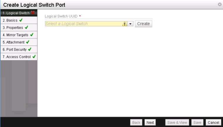
Logical Switch UUID: The UUID of the logical switch you want to connect the physical server to.

Provide a name for the Logical Switch Port
Next

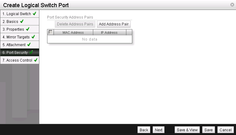
Attachment Type: VTEP L2 Gateway
VTEP L2 Gateway Service UUID: The UUID of the GW Service created above
VLAN: 0
Since we are using an access port on the arista switch, we leave the vlan 0 or empty.
The Arista VTEP will map the VXLAN VNI automatically to the vlan that is configured on the switch port. In our example VLAN 200
If a trunk port on the TOR Switch is used instead, the value you enter in this field, would be provisioned dynamically on the switch/trunk port.

Next
Click Save & View
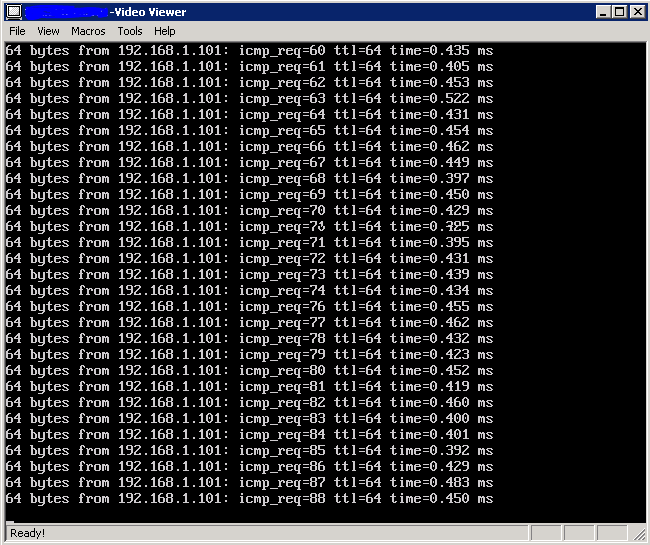
Let’s have a look at the outcome of the configuration.
The following printscreens of the RSA of the physical Blade Server and the console screenshot of the OpenStack instance show, that the communication is successful.

Ping:
Source: physical server (192.168.1.10)
Target: VM1 (192.168.1.101)
And of course, the communication workes as well the opposite way:
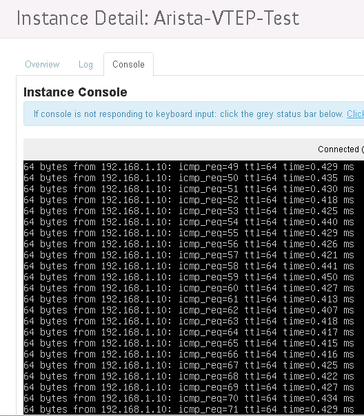
Source: VM1 (192.168.1.101)
Target: Physical server (192.168.1.10)

I am a senior consultant at d-fens specialised in infrastructure automation.


Very cool, thanks for sharing this Fabian!